
Learn how to troubleshoot VFD overcurrent faults safely. Step-by-step guide to isolate causes, reset drives, and prevent recurring trips
An overcurrent fault can be either an instantaneous short-circuit event or a sustained overload or control-setting problem. Eaton's guidance places configurable current limit as high as 200% of rated current, while instantaneous trip thresholds vary roughly from 260% to 400%, depending on drive size, so record the exact fault code, trip speed, output frequency, current, DC-bus voltage, and load state before touching anything.
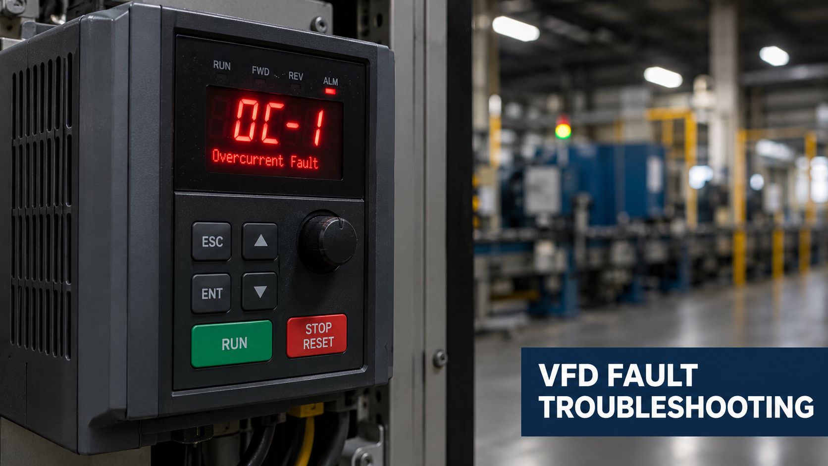
The conveyor is stopped, the operator is asking for a reset, and the production team is waiting for an answer. The display says OC, but that code doesn't tell you whether a motor cable is damaged, a bearing is binding, acceleration is too aggressive, or the drive's own current feedback has failed.
A reset may get the line moving, but it also removes evidence and can turn a developing electrical or mechanical fault into damaged power hardware. Treat the first trip as a diagnostic event. Capture the operating context, isolate the equipment safely, and use the trip conditions to rank the likely causes rather than working through an unfocused checklist.
Table of Contents
- When the Drive Trips and the Line Stops
- Safe Isolation and Initial Inspection Steps
- Reading Fault Context to Rank Likely Causes
- Performing the Motor Disconnection Test Safely
- Why Recurring Faults Point to Installation or Process Issues
- Preventive Maintenance and Professional Support Options
When the Drive Trips and the Line Stops
A maintenance supervisor sees an overcurrent code during conveyor startup. The first instinct is often to press reset, clear the alarm, and see whether the machine runs. That approach sometimes restores production, but it tells you very little. If the conveyor starts after the reset, the underlying problem may still be a loose terminal, a failing bearing, a jammed transfer point, or insulation that breaks down only when the cable moves or warms.
Start with the record, not the reset. Write down the exact fault code shown by the drive, the motor speed or output frequency at the instant of the trip, the measured current, the DC-bus voltage, and whether the drive was accelerating, decelerating, or running steadily. Add recent maintenance, parameter changes, process changes, and the key distinction between a trip with no process load and a trip only when the machine is working.
Build a useful fault snapshot
The fault history should answer what the drive was being asked to do. A code that appears at zero or very low speed has a different diagnostic priority from one that appears after the motor has reached steady speed.
Record these details before clearing the event:
- Exact code: Manufacturer codes and subcodes can distinguish operating conditions or protection functions.
- Trip speed and frequency: Note whether the motor had begun turning and whether the output frequency was changing.
- Electrical values: Capture current and DC-bus voltage if the drive provides them.
- Process state: Record valve positions, conveyor loading, pump condition, damper position, or any other event that changed the torque demand.
- Recent history: Include motor work, cable work, parameter edits, cleaning, water exposure, and mechanical maintenance.
Practical rule: A reset is a recovery action, not a diagnosis. Preserve the evidence first.
Eaton's VFD fault-code guidance supports separating instantaneous overcurrent from sustained overload and parameter problems. That distinction prevents a common mistake, replacing a motor or drive when the timing of the trip already points toward a different part of the system.
Safe Isolation and Initial Inspection Steps
Safety comes before the fault tree. A VFD can retain dangerous energy after the incoming supply is removed, and the motor circuit can remain hazardous even when the keypad is dark. Follow the site's lockout/tagout procedure, isolate every relevant energy source, and use the manufacturer's instructions for discharge time and verification.
Isolate before opening the circuit
Apply lockout/tagout and prevent anyone from re-energizing the equipment while testing is under way. After the required waiting period, verify the absence of voltage with an appropriately rated meter, including the DC bus and the output terminals. Don't rely on the display, a control switch, or the assumption that the capacitors have discharged.
Before disconnecting motor leads, identify and label the U, V, and W conductors. Disconnecting the wrong circuit or leaving a conductor loose can create a second fault during the investigation. If the equipment is part of a larger automated cell, account for stored mechanical energy, gravity, pressure, and any backfeed from another source.
Inspect the complete motor circuit
Look at the drive output terminals, the cable route, junction boxes, motor terminal box, and the motor itself. Search for evidence that a quick visual check often misses:
- Phase faults: Check for phase-to-phase and phase-to-ground damage in the U/V/W circuit.
- Insulation damage: Look for chafing, crushed cable, heat damage, oil attack, and abrasion near glands or moving equipment.
- Terminations: Check for loose terminals, discoloration, arcing marks, and incorrect connections.
- Moisture and contamination: Inspect junction boxes, glands, conduit entries, and the motor terminal box for water, condensation, dust, or conductive deposits.
- Motor connection: Confirm that the winding connection matches the drive's intended output and the motor nameplate.
A megohmmeter can damage drive electronics if the drive remains connected. Isolate the drive first, then test the motor and cable separately with an insulation tester using voltage appropriate to the equipment and the motor manufacturer's procedure. Compare phase resistance and insulation results with the motor manufacturer's limits, not with a universal pass-or-fail number.
Never apply insulation-test voltage through the connected VFD. Disconnect the drive before testing the motor circuit.
If moisture, damaged insulation, or a loose connection is found, correct the condition before energizing anything. A clean-looking cabinet doesn't prove the cable, junction box, or motor is healthy under vibration, heat, or process load.
Reading Fault Context to Rank Likely Causes
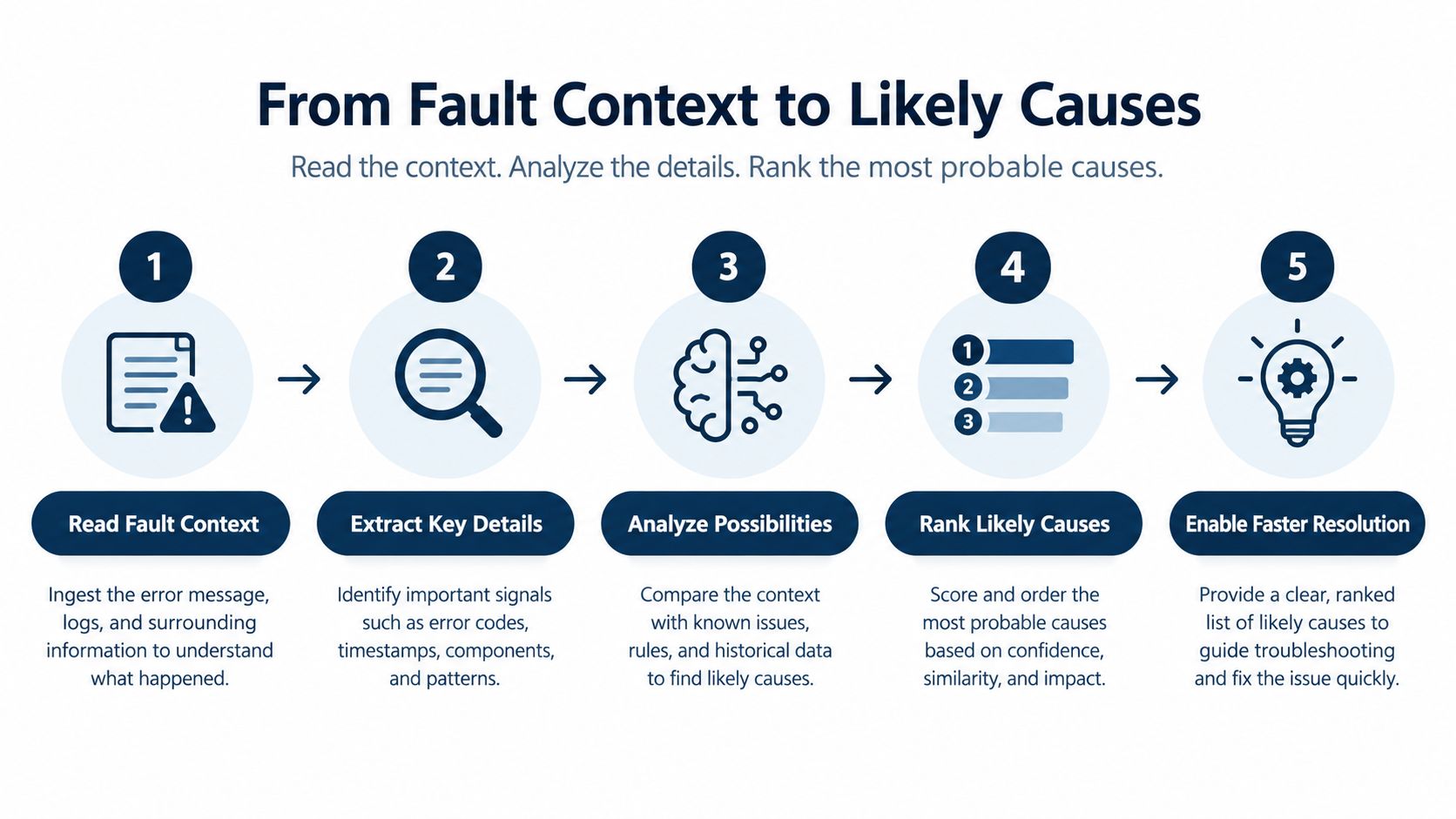
The most useful question isn't "What causes an overcurrent fault?" It's, "What was the drive doing when the current crossed its protection limit?" Trip timing narrows the search because the motor, load, controls, and power stage behave differently at startup, during acceleration, and at steady speed.
A practical ranking starts with the fault-history record. Compare current, voltage, output frequency, temperature, and process state at the event. Then classify the trip into one of three broad patterns.
Instantaneous trips at low speed
A trip as soon as modulation begins, before the motor has meaningfully accelerated, raises the priority of an output short, ground fault, locked rotor, or power-stage problem. Inspect the motor cable and windings after safe isolation. If the motor and cable are separated from the drive and the same behavior remains, internal drive diagnosis becomes more likely.
A locked rotor can look electrical from the keypad because the drive responds to a sharp current demand. Check the driven machine for a jam, seized bearing, blocked pump, or mechanical obstruction rather than assuming the motor windings are shorted.
Trips during acceleration
Acceleration faults demand a different line of reasoning. The drive is increasing frequency and torque while overcoming inertia, friction, and process resistance. A short ramp, incorrect motor data, excessive torque demand, mechanical binding, or an unsuitable duty rating can push current beyond the protection limit.
Verify the motor nameplate voltage, current, frequency, and relevant control parameters. Check acceleration time against the actual load, not against a setting copied from another machine. Torque boost, vector parameters, and autotune status also deserve review, but parameter changes should follow evidence. Raising current limits or adding torque without finding the mechanical cause can conceal a deteriorating machine.
Trips at steady speed
A steady-speed trip points toward a changing process load, mechanical degradation, inadequate drive duty, or an electrical problem that appears under heat or sustained stress. Correlate the event with bearing temperature, vibration, material flow, valve movement, pump condition, or another process transition.
Use this VFD fault-code reference to confirm the meaning of the displayed code, but don't diagnose from the label alone. A code identifies the protection response, not necessarily the failed component.
Deceleration events need their own review. A high-inertia load can force energy back toward the DC bus as it slows, and the resulting protection response may be reported alongside current or bus-voltage information. Check the deceleration state and DC-bus trend before treating the event as a motor short.
Performing the Motor Disconnection Test Safely
The motor-disconnection test is valuable because it separates the external motor circuit from the drive output stage. It isn't a casual “remove the wires and try again” exercise. An unsafe test can expose personnel to live conductors, damage the drive, or create a misleading result.
Set up a controlled test
Begin with lockout/tagout and follow the OEM isolation procedure. Wait for the specified discharge period, measure the DC bus, and verify zero voltage at the points required by the procedure. Only then should qualified personnel disconnect and label the motor leads.
Inspect the disconnected conductors and terminals before restoring power. The test plan should state what the drive will be commanded to do, which protective settings remain active, and how the result will be recorded. Don't use repeated reset-and-run attempts as a substitute for a controlled test.
With the motor leads isolated, perform the reset or run test only if the manufacturer permits it. Keep the test unloaded and brief, and stop immediately if the drive behaves unexpectedly, shows abnormal current, or produces a new alarm.
Interpret the result carefully
If the overcurrent fault disappears with the motor disconnected, the problem is more likely in the motor, cable, connection, or driven machinery. That result doesn't prove the drive is healthy under operating conditions. Continue with separate motor and cable tests, verify phase resistance and insulation, and inspect the mechanical train for binding or locked-rotor conditions.
If the fault persists while the output is unloaded, prioritize the drive's internal path. Possible areas include current sensors, gate drivers, IGBTs or power cells, the DC bus, and the control board. These checks require appropriate electrical skills, test equipment, and manufacturer procedures. A power-stage inspection isn't a safe extension of a basic maintenance reset.
A no-load pass narrows the fault. It doesn't authorize an immediate return to production.
Before reconnecting, confirm terminal identification, connection torque, cable condition, and the motor's nameplate data in the drive. Then test under controlled conditions while monitoring current, frequency, temperature, and process load. If the result is ambiguous, stop rather than forcing a conclusion from one unloaded run.
Why Recurring Faults Point to Installation or Process Issues
A drive that trips once may have suffered a single abnormal event. A drive that trips repeatedly after resets or parameter changes is giving you a pattern. The repeatability often points beyond the keypad and into the installation, environment, or machine.
Moisture can enter a junction box and disappear from view after the cabinet warms. A loose termination can behave normally during a stationary inspection, then open or arc when vibration changes the contact. Cable routing near heat, sharp edges, moving equipment, or high-interference sources can create a fault that appears only at a particular speed or temperature.
Look for conditions that change with operation
Mechanical faults can be equally deceptive. Bearing degradation, coupling misalignment, gearbox binding, a clogged pump, or a changed process load may increase torque demand without producing a visible electrical short. The current trend may rise gradually, while a reset temporarily restores operation.
Track the conditions around each event rather than treating every trip as independent:
- Trip frequency: Note whether events are becoming more frequent or clustering around a shift, product, or process step.
- Comparable load current: Compare current at similar speeds and process conditions.
- Cabinet temperature: Record heat conditions, ventilation status, fan operation, and contamination.
- Insulation readings: Trend motor and cable results using the same method and equipment.
- Vibration and maintenance history: Correlate electrical events with bearing, coupling, gearbox, and alignment work.
The guidance on recurring drive overcurrent faults emphasizes installation and process factors such as moisture, loose connections, grounding, ventilation, contamination, and mechanical changes. Those factors matter because a no-load test can clear the alarm while the actual machine remains unsafe or mechanically compromised.
Resist the easy parameter fix
Increasing acceleration time or current limit can be appropriate after the mechanical and electrical condition is known. It isn't a root-cause method. A higher limit may mask insulation breakdown, a jammed process, a failing bearing, or a drive that isn't correctly sized for the duty.
Build a timeline that includes maintenance work, production changes, weather or humidity, cleaning activity, and previous resets. When a fault returns, the question isn't only why the drive tripped today. It's what changed between the last successful run and the present event, and why the same protection response keeps appearing.
Preventive Maintenance and Professional Support Options
Preventive maintenance works best when it targets the conditions that create overcurrent, not just the fault message. During planned shutdowns, inspect cabinet cleanliness, cooling paths, fans, terminals, cable entries, motor junction boxes, and the mechanical load. Review saved parameters against approved settings and confirm that the motor data still matches the installed motor.
Thermal stress and contamination deserve particular attention. Dust can restrict cooling, moisture can reduce insulation strength, and loose connections can generate heat before they produce a visible failure. A maintenance record should connect drive alarms with motor tests, mechanical inspections, cabinet conditions, and corrective actions.
Choose the service response to the evidence
A simple external issue may need a qualified plant technician to repair a termination, correct a connection, remove a blockage, or restore the approved parameters. A suspected power-stage or feedback problem needs a more controlled repair path, especially when the drive trips unloaded or when current readings don't agree with independent measurements.
The useful service models are distinct:
- Rapid Restore: Structured on-site diagnosis, fault-record review, electrical and thermal inspection, and controlled restart after the likely failure path is understood.
- Deep Repair: Workshop disassembly, bench diagnostics, component-level repair, and functional testing when the power stage, sensors, gate drivers, or control assemblies require deeper work.
- Preventive Care: Planned inspection and condition checks during shutdowns to address contamination, thermal stress, aging, and recurring fault patterns before they stop production.
A lifecycle approach is more defensible than replacing the entire drive after every alarm. It preserves the distinction between a motor or process problem, a serviceable subsystem, and a genuine power-stage failure. The principles in this guide to preventive and corrective maintenance are most useful when the site turns them into documented inspection intervals, test records, and restart criteria.
DUCHENG Industrial provides multi-brand VFD diagnosis, on-site restoration, workshop repair, preventive inspections, reconditioning, spare-parts support, and controlled functional verification for industrial facilities. The right escalation point is reached when safe isolation, evidence-based testing, and qualified plant resources can't explain the fault or restore reliable operation.
If your VFD overcurrent fault keeps returning, send DUCHENG Industrial the fault history, trip conditions, motor and drive details, and recent maintenance record for structured review. Visit DUCHENG Industrial to discuss Rapid Restore, Deep Repair, or Preventive Care support for the affected drive and its wider motor system.