
Learn how VFD used in industry cuts energy, controls process and stays reliable. Applications, benefits, failures and lifecycle tips for plant teams.
A production line stops just after shift change. The operator sees a drive fault, the motor coasts down, and the maintenance team starts asking the same urgent questions: Was the motor overloaded? Did the incoming power dip? Is the drive overheating, or did the cable insulation fail? A reset might bring the machine back, but it won't explain why the trip occurred or prevent a repeat outage.
That's the reality behind VFD used in industry applications. A variable frequency drive is more than a motor speed controller. It's an electrical, mechanical, process, and reliability asset that must be matched to the load, installed for the environment, and maintained throughout its service life. This guide follows that practical path, from the drive's internal operation to industrial applications, energy decisions, integration checks, failure prevention, and lifecycle service.
Table of Contents
- Introduction to VFDs on the Plant Floor
- How a VFD Controls Motor Speed and Torque
- Where VFDs Are Used Across Heavy Industry
- Energy Savings and Process Control Benefits That Matter
- How to Select and Integrate a VFD for Your Application
- Common Failure Modes and How to Prevent Them
- Keeping VFDs Running Through Their Full Lifecycle
Introduction to VFDs on the Plant Floor
A VFD sits between the electrical supply and an AC motor, controlling the frequency and voltage delivered to the motor. By changing those electrical conditions, the drive lets the motor accelerate smoothly, run at the speed the process requires, and decelerate under controlled conditions instead of receiving a fixed-speed start every time.
That capability explains why the technology has become a major industrial platform rather than a specialist accessory. One 2025 estimate places the global VFD market at USD 23.85 billion, with a projection of USD 40.97 billion by 2034 at a 6.09% CAGR. The same estimate reports that Asia Pacific represented 41.06% of the market in 2025. A separate estimate values the market at USD 24.7 billion and projects USD 32.0 billion by 2030 at a 5.3% CAGR, showing that published market forecasts vary while still describing a large and expanding equipment base across manufacturing, oil and gas, HVAC, and process industries. These figures are reported in the variable frequency drive market estimate.
For plant teams, market size matters less than application quality. A correctly applied drive can help a pump follow changing demand, let a conveyor start without jolting its load, or regulate a fan without wasting energy across a throttling device. A poorly applied drive can create harmonics, motor insulation stress, nuisance trips, and difficult troubleshooting.
Reliable operation usually has four characteristics:
- The application is understood: The team knows whether the load needs variable torque, constant torque, or regenerative control.
- The installation matches the site: Enclosure protection, cooling, grounding, cable routing, and harmonic mitigation fit the environment.
- The process data is visible: Operators can identify the demand signal, operating range, fault history, and actual duty cycle.
- The lifecycle is planned: Maintenance, spare parts, repair, upgrade, and replacement decisions happen before a critical failure.
Practical rule: A VFD should be specified as part of a motor-driven system, not as an isolated electrical box.
How a VFD Controls Motor Speed and Torque
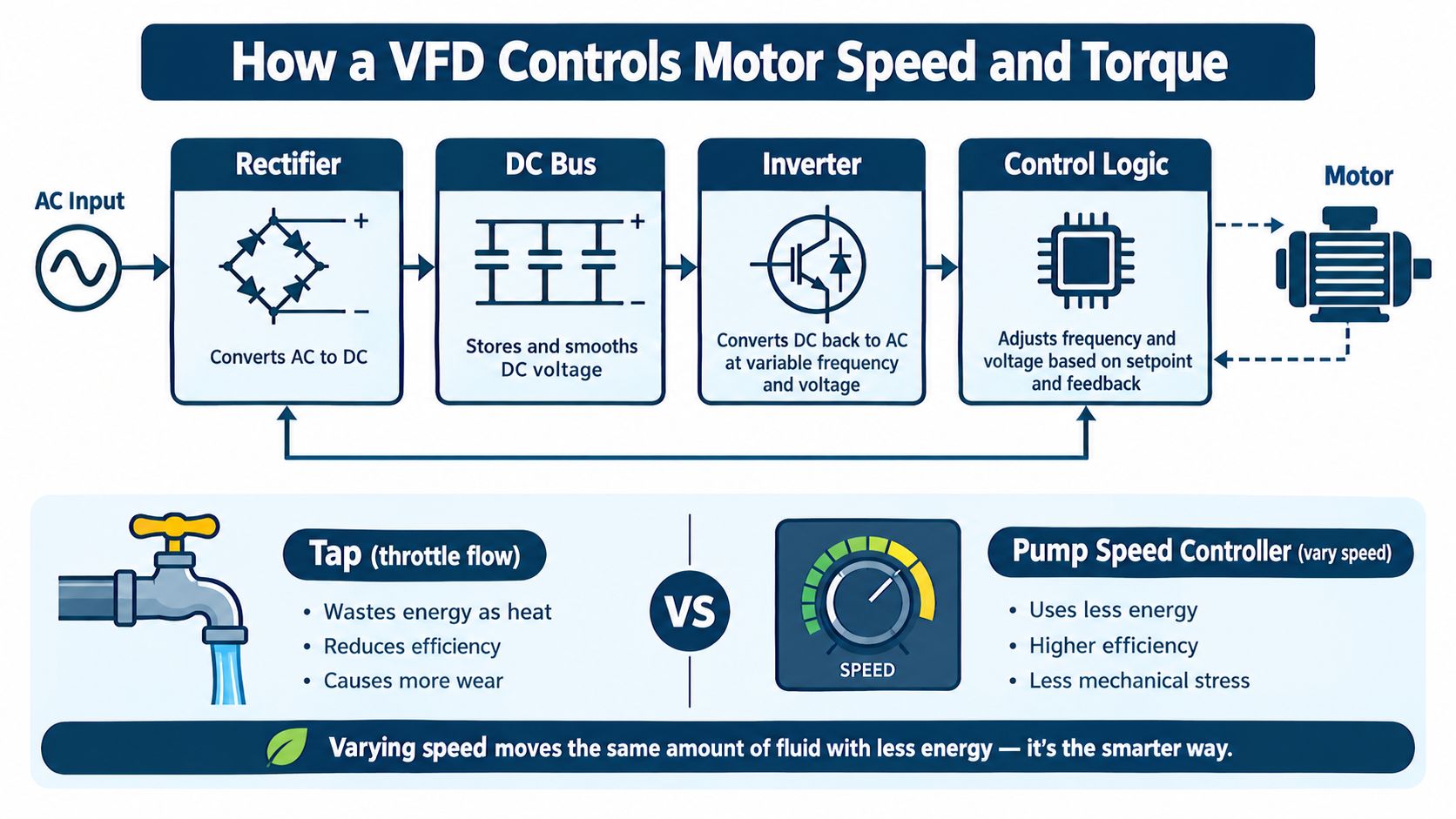
Start with a simple comparison. A valve can reduce liquid flow by creating resistance in a pipe, much like turning down a tap while a pump continues pushing. A VFD takes a different approach. It reduces the pump motor's speed so the machine produces less flow in the first place.
The first method controls the process by wasting available energy across a restriction. The second changes the motor's operating point. This distinction is especially important for centrifugal pumps and fans, where power changes sharply as speed changes.
The three power stages
A VFD converts fixed-frequency AC input into controlled AC output through three main stages:
- Rectifier: Diodes convert incoming AC into DC. The rectifier acts like a one-way electrical gate, changing alternating current into current that flows in one direction.
- DC bus: Capacitors smooth the rectified power and provide an energy reservoir between the input and output sections.
- Inverter: Electronic switches convert DC back into AC. The control system varies the switching pattern to produce the required output frequency and voltage.
The inverter doesn't send the motor a simple, utility-style sine wave. It creates a pulse-width-modulated waveform whose effective frequency and voltage determine motor behavior. Raising frequency generally raises motor speed, while lowering frequency slows it. The control system can also use a speed reference, pressure signal, flow feedback, torque demand, or another process value to adjust output automatically.
Why load type changes the answer
A variable-torque load, such as a centrifugal pump or fan, usually needs less torque as speed falls. A constant-torque load, such as a conveyor, mixer, or extruder, can continue requiring substantial torque even when operating more slowly. The drive must therefore be selected for the application's current, overload, acceleration, braking, and thermal requirements, not the motor nameplate power.
For a practical discussion of scalar, vector, sensorless, and closed-loop choices, see this guide to VFD control methods. The key point is that control mode affects both process response and commissioning effort. A simple fan may need only straightforward speed regulation, while a tension-sensitive line or heavy conveyor may require tighter torque control and carefully tuned acceleration.
Where VFDs Are Used Across Heavy Industry
The most useful way to understand VFD used in industry is to start with the machine problem, not the drive catalog. Ask what the process is trying to control: speed, pressure, flow, tension, mixing intensity, acceleration, or synchronization. The VFD earns its place when changing motor speed solves that problem more directly than a fixed-speed motor with mechanical regulation.
Steel and metal processing
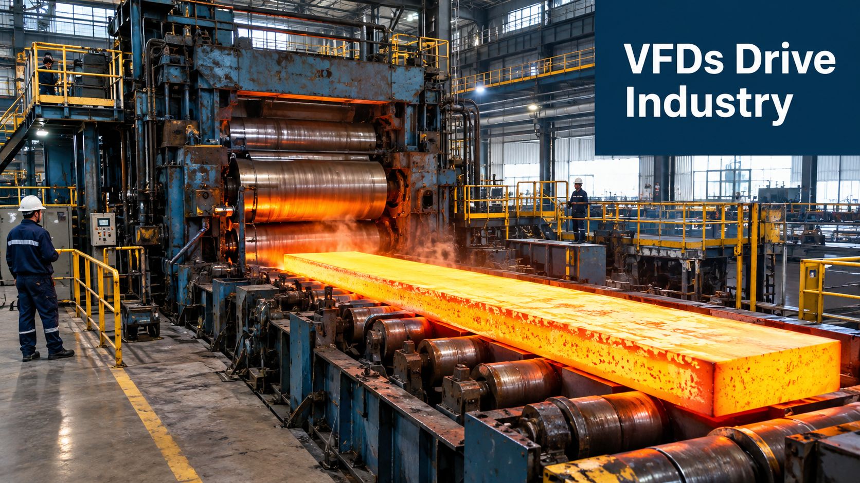
A rolling mill needs coordinated movement, controlled acceleration, and stable torque while material passes through rolls. VFDs can control mill drives, transfer tables, conveyors, cooling-water pumps, and exhaust fans. On a conveyor, controlled acceleration reduces product movement and mechanical shock. On a pump, speed feedback can follow process demand instead of forcing a fixed-speed motor to run against a throttled valve.
Steel sites also expose drives to heat, dust, vibration, and demanding production schedules. Cabinet cooling, filter access, cable termination, and separation from heat sources become part of the drive specification. For medium-voltage systems, the physical size and transport risk of the equipment can also shape the repair strategy.
A rolling line may have one drive regulating the process and another supporting auxiliary equipment. The correct solution isn't always a high-performance control mode everywhere. Engineers should identify which axes need tight speed or torque response and which auxiliary loads mainly need efficient variable-speed operation.
Tire and rubber manufacturing
Mixers, extruders, calenders, conveyors, and cooling systems all present different control requirements. A mixer may need repeatable speed and torque through a changing material batch. An extruder may require stable screw speed to support consistent output. Conveyors may need synchronized starts and stops to prevent material accumulation.
Rubber plants can also expose electrical cabinets to carbon black contamination. Conductive dust can settle on heat sinks, filters, terminals, and circuit boards, reducing cooling performance and increasing the risk of tracking or insulation problems. Enclosure selection alone won't solve the issue. Maintenance access, filtered airflow, cabinet pressure strategy, cleaning methods, and inspection frequency must work together.
Chemical plants and utilities
Chemical processes rely on pumps, fans, compressors, agitators, and dosing equipment. A VFD can follow pressure or flow demand, support controlled ramping, and reduce sudden hydraulic or mechanical changes. The process engineer still has to confirm that the pump, seal system, motor, and control loop remain suitable across the proposed speed range.
Utilities use drives in water movement, ventilation, cooling, and air systems. A fan running against dampers may be a strong candidate for speed control if demand varies across the operating day. A compressor can be more complicated because minimum speed, lubrication, unloading behavior, and process pressure stability may constrain the usable range.
High salinity adds another layer of risk. Salt-laden air can accelerate corrosion on cabinets, terminals, heat exchangers, and cable glands. The electrical team should treat corrosion control and thermal management as part of application engineering, not as post-installation housekeeping.
A short process walkdown should record:
- Driven equipment: Pump, fan, compressor, conveyor, mixer, extruder, or rolling drive.
- Control method: Valve, damper, bypass, mechanical coupling, on-off cycling, or existing speed control.
- Demand variation: Whether the process needs different speeds during normal production.
- Site exposure: Heat, dust, moisture, salinity, washdown, vibration, and restricted cabinet access.
- Consequence of failure: Whether a fault stops one machine, a production cell, or a critical utility.
Energy Savings and Process Control Benefits That Matter
A VFD doesn't create savings because it is connected to a motor. The load profile determines the opportunity. A pump or fan that runs at different speeds to meet changing demand can offer a strong case, particularly when operators currently use throttling, dampers, or bypass flow. A constant-speed machine that operates near one stable point may deliver a much smaller energy benefit.
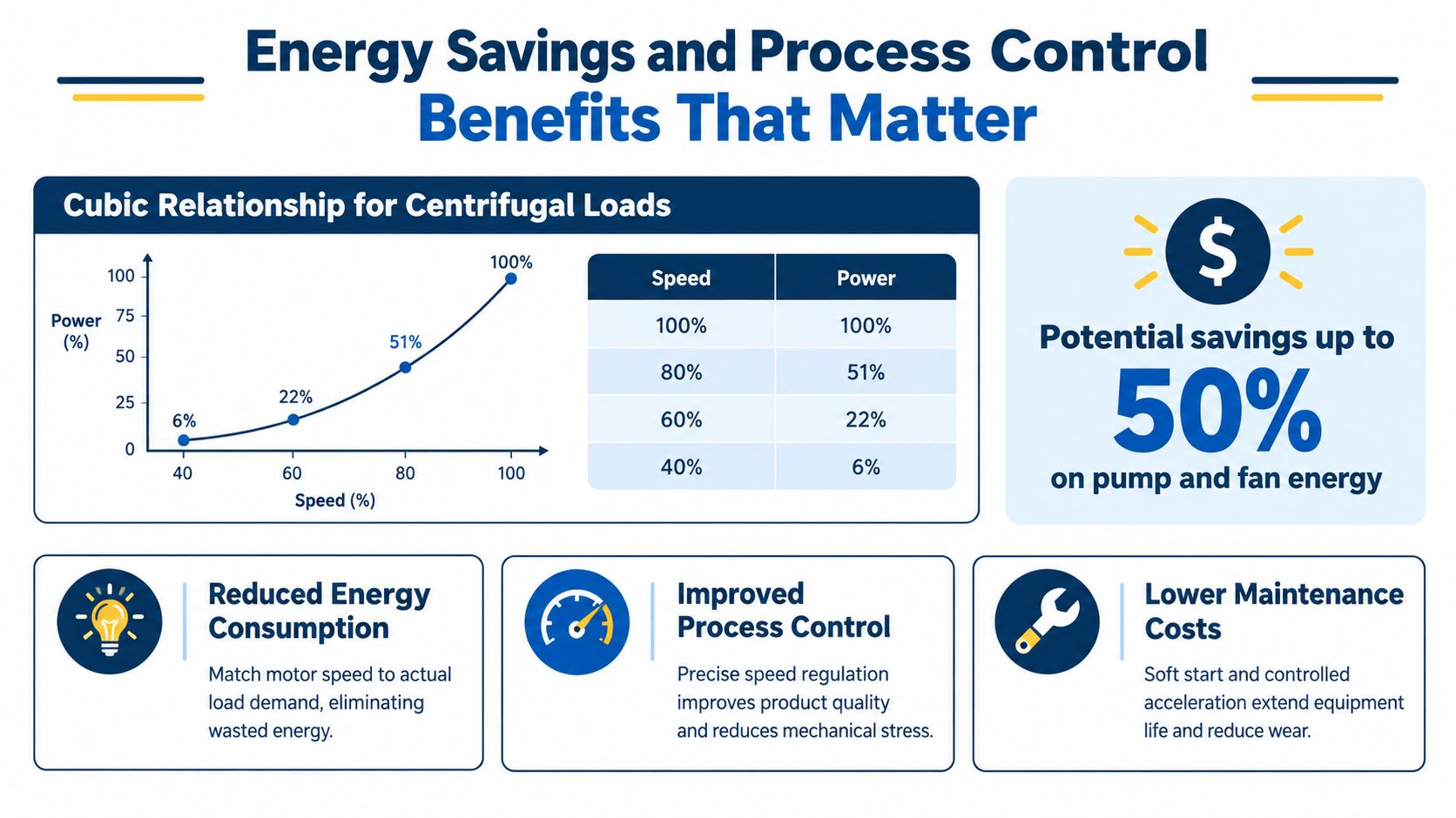
For centrifugal equipment, pump and fan power follows an approximately cubic relationship with speed. That means a moderate speed reduction can produce a disproportionate reduction in power demand. The relationship is a useful screening principle, not a guarantee. Actual results depend on the system curve, control target, motor efficiency, drive losses, operating hours, minimum speed, and whether the process can accept the changed operating point.
Independent technical analysis reports typical VFD energy reductions of 5% to 15%, with some applicable systems achieving 20% to 65% savings. The same source emphasizes that the strongest opportunities occur when speed control replaces throttling or bypass operation. These ranges are documented in the technical analysis of VFD energy savings.
Test the duty before calculating payback
Before approving a retrofit, collect operating information rather than relying on a generic savings promise.
- Record operating points: Capture speed, flow, pressure, current, and process demand across representative production conditions.
- Identify the restriction: Confirm whether a valve, damper, or bypass is absorbing excess output from a fixed-speed motor.
- Measure run time: A drive operating for long periods at reduced demand deserves more attention than an intermittently used auxiliary motor.
- Check process limits: Confirm minimum flow, cooling, lubrication, seal, and motor-speed requirements.
- Model the baseline: Use measured demand and the existing control method, not only the motor's rated capacity.
A separate Fraunhofer and CEMEP study estimated that optimal use of variable speed drives in the European Union could save 121.1 TWh of electricity annually, equivalent to 9% of annual electric motor consumption. Its estimated opportunity included 36.0 TWh from pumps, 70.3 TWh from fans, and 15.1 TWh from compressors, as reported in the Fraunhofer and CEMEP motor-saving study.
Efficiency is only one benefit
A VFD can also provide soft starting, controlled stopping, smoother acceleration, and better speed regulation. Those functions can reduce belt shock, coupling stress, hydraulic surges, and product disturbance. In a mixer or conveyor, stable speed may improve repeatability even when the direct energy case is modest.
Decision test: If the process demand varies and the existing system controls excess output mechanically, investigate the retrofit. If the motor runs at nearly constant speed for a fixed mechanical duty, validate the control benefit before assuming major savings.
How to Select and Integrate a VFD for Your Application
Selection starts with the motor and the driven machine. Match the drive to motor voltage, current, phase, speed range, overload requirement, acceleration profile, braking behavior, and environmental conditions. A drive selected only by nominal motor power can be unsuitable if the load has high starting torque, frequent acceleration, poor ventilation, or a demanding duty cycle.
Voltage class affects architecture, isolation, clearances, service practices, and site safety requirements. Low-voltage drives may fit common plant motors, while medium- and high-voltage systems require more deliberate engineering around switchgear, motor insulation, cable systems, protection, and field service access. The right class is dictated by the motor and distribution system, not by a preference for a particular drive format.
Use the application factor matrix
| Application Factor | What to Check | Recommended Action |
|---|---|---|
| Load type | Variable torque or constant torque | Select the appropriate duty rating and verify overload requirements |
| Motor data | Nameplate voltage, current, frequency, speed, and connection | Size from motor current and application duty, not power alone |
| Operating range | Minimum and maximum speed, starts and stops, acceleration time | Confirm motor cooling, lubrication, resonance, and control stability |
| Run profile | Hours at full, reduced, and changing demand | Build the energy case from measured duty-cycle data |
| Environment | Heat, dust, moisture, salinity, vibration, and washdown | Choose enclosure, cooling, filtration, and corrosion protection accordingly |
| Input power | Voltage variation, short-circuit level, and upstream disturbances | Review protection, line reactors, and harmonic requirements |
| Motor cable | Length, shielding, grounding, routing, and insulation condition | Use suitable cable and output filtering where required |
| Process criticality | Consequence of drive failure and available redundancy | Consider bypass arrangements, spares, or an engineered recovery plan |
Engineer the electrical interface
VFDs are nonlinear loads, so they can affect upstream power quality. The U.S. Department of Energy identifies total harmonic distortion, or THD, as a common way to measure harmonics from nonlinear loads such as VFDs. Sensitive equipment is often designed around approximately 5% THD, and the same guidance recommends mitigation such as 3% input-line reactors and output filters when motor-lead distances exceed roughly 50 feet. These values and recommendations appear in the Department of Energy motor systems sourcebook.
The installation team should also separate power and control wiring, use suitable shield termination, establish a low-impedance grounding path, and manage cabinet heat. Long motor leads can produce reflected-wave stress and higher voltage rise at the motor terminals. An output reactor or filter may be needed after checking the drive, motor, cable, and manufacturer requirements.
Commission with measured values
Enter the motor nameplate data accurately. Verify rotation, ramp times, current limits, feedback scaling, interlocks, minimum speed, and fault responses. Test the drive under actual process conditions, then record baseline current, temperature, vibration, speed, and process response for later comparison.
Common Failure Modes and How to Prevent Them
A VFD in a dusty plant can trip during the hottest shift, while the cause sits outside the drive cabinet. Repeated trips usually reflect thermal stress, contamination, electrical disturbance, mechanical loading, or aging components. Resetting the drive without recording the fault can turn an early warning into a damaged power stage and another production stop.
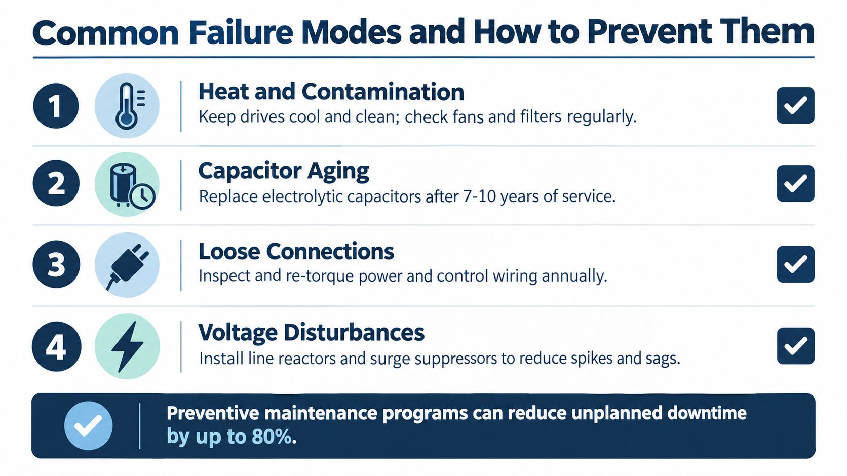
Common failure mechanisms include:
- Heat and contamination: Blocked filters, dirty heat sinks, failed cooling fans, and conductive dust raise internal temperature and restrict cooling.
- Aging capacitors: Electrolytic capacitors lose performance over time. Maintenance planning commonly considers replacement around 7 to 10 years, as discussed in this industrial VFD maintenance guide.
- Loose connections: Loose power or control terminals create resistance, heat, intermittent signals, and arcing risk.
- Voltage disturbances: Spikes, sags, imbalance, and upstream faults stress rectifiers, capacitors, and inverter components.
- Shaft currents: High-frequency switching can create bearing-current paths unless motor grounding and bearing protection are suitable.
- Reflected-wave stress: Long motor cables increase insulation stress and voltage rise at the motor.
- EMI from poor routing: Parallel power and control wiring can add noise to feedback, communications, and discrete signals.
Diagnose before restarting
Record the fault code, operating state, output frequency, motor current, process condition, and recent maintenance activity. Inspect the motor, load, cable, supply, cooling path, and enclosure before concluding that the drive has failed. An overcurrent trip may come from a jammed machine or damaged motor cable. An overtemperature trip may indicate a blocked filter rather than a failed power module.
A case study recorded THD rising from approximately 13% to 30% when a fan motor operated with a VFD. The example, reported in this harmonic failure modes reference, shows why efficiency gains and power-quality engineering belong in the same review. A drive can improve process control while raising harmonic stress unless mitigation, such as line reactors or filters, is installed.
Make prevention site-specific
A conditioned electrical room needs a different maintenance approach from a rubber plant exposed to carbon black or a coastal utility exposed to salt-laden air. Inspect filters, fans, heat sinks, terminals, cable glands, grounding points, and enclosure seals according to actual contamination and thermal conditions.
Harsh service also changes the repair decision. A workshop repair may suit a removable low-voltage unit, while on-site MV reconditioning can reduce handling and transport exposure when a medium-voltage drive is difficult to ship. That choice connects failure prevention with lifecycle service economics: avoiding a preventable trip matters, but so does selecting a practical recovery path before the drive reaches late life.
Reliability insight: The best maintenance interval is the one that catches contamination and temperature changes before they appear as a production fault.
Keeping VFDs Running Through Their Full Lifecycle
A reliable VFD program begins at commissioning and continues through late-life service. During startup, the team should verify parameters, control signals, motor rotation, acceleration, feedback, protections, and process response. Production escort during a critical restart can catch abnormal current, temperature, vibration, or control behavior before the equipment returns to unattended operation.
For an unplanned trip, rapid restoration should still follow structured diagnosis. Record the fault history, isolate the drive safely, check external causes, verify parameters, and restart only after the team understands the risk. During planned shutdowns, preventive care can address contamination, cooling, connections, insulation stress, and aging components before they become an outage.
A complete service path may include:
- Field diagnosis and controlled restart: Resolve external causes and confirm safe operation.
- Workshop deep repair: Disassemble, test, repair components, verify the power stage, and conduct functional testing.
- On-site MV reconditioning: Recondition medium- and high-voltage drives at the plant when shipment is impractical or transport creates additional risk.
- Spare and obsolescence planning: Identify compatible parts, verify exchange units before dispatch, and assess upgrades against replacement.
- Condition-based support: Build monitoring and data arrangements around the drive's actual failure risks and process criticality.
For maintenance routines covering inspection, troubleshooting, and service planning, use this guide to variable frequency drive maintenance. The important shift is from reactive replacement to lifecycle decisions. A serviceable subsystem may be repairable or reconditionable even when a whole-unit changeout appears faster on paper.
DUCHENG Industrial provides multi-brand commissioning, emergency response, workshop repair, preventive maintenance, and on-site Blue Reconditioning for industrial VFD assets, including medium- and high-voltage systems. Plant teams can also use its field and workshop service coordination, spare-parts verification, upgrade assessments, and Smart O&M consulting to plan recovery and late-life support.
Review your critical drives against their actual load profile, environment, fault history, and spare-parts position before the next outage. For commissioning support, structured troubleshooting, workshop repair, or on-site medium- and high-voltage reconditioning, visit DUCHENG Industrial and discuss the drive assets that matter most to your plant.